Beyond capture: where PFAS destruction fits in semiconductor wastewater
Share this insight
As semiconductor manufacturers look for ways to manage PFAS-containing waste, destruction technologies are attracting interest. However, the challenge is less about breaking the carbon–fluorine bond but more about integrating that technology into an already complex semiconductor wastewater system.
Sarah Meyer, Chief Operating Officer at Enspired Solutions spoke to Ultrafacility about Enspired’s solution which uses Photoactivated Reductive Defluorination (PRD),a patented chemistry, to destroy PFAS and discussed retrofitting into existing semiconductor facilities.
Can you introduce Enspired Solutions and where the technology is today?
In 2022, we contract designed and built our first PFASigator®,the equipment we use to apply PRD, and commissioned that in 2023 with our first field test at an industrial manufacturing facility in Michigan.
Since then, we’ve been doing extended pilot tests for multiple industries. We sold our first machine in 2024, and it’s being used by an environmental services company doing fire truck cleanouts and treating AFFF-impacted waters. To date, we have tested our technology at both the bench scale and field scale on more than 200 unique waters. These encompass landfill leachates, groundwater, surface waters, municipal and industrial wastewaters like semiconductor, fire truck and fire system rinseates, AFFF, and a few other specialty things that are in the industry.
How does the technology work?
It is a UV-based technology, with two UV reactors mounted on the skid. Concentrated PFAS solution enters the PFASigator, reagents are added, and the solution is circulated past the UV lamps, where destruction takes place.
Depending on the complexity of the water, circulation can take as little as 20 minutes or several hours. Once the destruction target is reached, the treated water is discharged for any remaining treatment needed for other constituents.
The system also has an onboard ion-selective electrode, which monitors fluoride production as carbon-fluorine bonds are broken. That allows us to track the destruction reaction in real time. We meet targets that are one to two orders of magnitude PFAS destruction across long-chain, short-chain and ultra-short-chain compounds.
What is photoactivated reductive defluorination?
Most PFAS destruction technologies are oxidative, but PRD is a reductive process. That means it uses a different destruction pathway and can lead to different byproducts.
The process does not require added heat or pressure, so the unit operates at atmospheric temperature and pressure. As the PFAS are destroyed, we generate ionic fluoride, which we monitor in real time, along with water and simple carbon molecules such as formic acid and acetic acid.
How does the technology fit into existing treatment systems?
When we designed the reactor, we asked the industry what they would want from a PFAS destruction technology. One clear message was that it needed to fit into existing treatment trains, rather than require a separate facility.
For a semiconductor fab generating wastewater every day, the most efficient configuration is likely to pair PRD with a separation and concentration technology, such as foam fractionation. That step strips PFAS out of the wastewater, allowing the treated water to be discharged if it meets the facility’s criteria. The resulting concentrate is then sent to the PFASigator for destruction, with any remaining PFAS returned for reconcentration.
If a facility is already treating for constituents such as metals or ammonia, the question becomes where the PFASigator should sit within the existing treatment train.
Metals or ammonia alone would not make PRD unusable, but they could influence where we would place the unit to optimise the destruction rate. The integration would therefore need to be assessed site by site.
What semiconductor-related samples have you tested?
We did benchtop studies on three semiconductor-related samples. The first was a PFBS-dominated wastewater containing high concentrations of tetramethylammonium hydroxide, or TMAH. The second was a reverse osmosis retentate with high levels of trifluoroacetic acid, or TFA. We also ran an in-lab destruction screening on a TARC product, a top anti-reflective coating supplied by the manufacturer.
The PFBS sample had an initial concentration of about 40,000 parts per trillion and was a complex matrix, with high TMAH, additional fluoropolymers and unidentified PFAS. We learned from the manufacturer that TMAH can interfere with oxidative destruction technologies, so they were looking for an alternative pathway.
The TFA sample was an RO retentate with a concentration of about 26 parts per million. It also had very high total dissolved solids, which is typical of RO retentate.
What did the semiconductor screening show?
When samples come into our laboratory, we can screen them by measuring fluoride release over increasing UV dose. Because fluoride is released as carbon-fluorine bonds are broken, that real-time signal gives us an indication of the PFAS destruction rate.
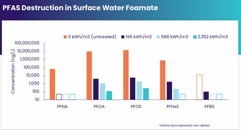
For the high-PFBS sample, the destruction rate was faster than our standard reference reaction, where we dose PFOA into deionized water. Despite the initial concentration and matrix complexity, we achieved 97% destruction of PFBS, and the treated concentration was below EPA’s 2,000 parts per trillion drinking water maximum contaminant level for PFBS.
The high-TFA RO retentate performed similarly to the reference reaction. The destruction rate was not quite as fast as the PFBS sample, but we still achieved more than 99% destruction, with a final concentration of non-detect. TFA is particularly important for the semiconductor industry because it is common in wastewater and, if water is reused within a facility, remaining TFA can create quality assurance problems in chip production.
The TARC product work was more limited. We estimated a fluoropolymer concentration of 1.8 parts per million in the product sample, which was diluted for treatment to approximate what might be present in facility wastewater. We saw a strong fluoride release curve, indicating a high rate of defluorination, but did not collect samples for third-party validation in that case.
We discussed low-volume spin bowl waste versus higher-volume downstream process waste. How would the treatment train differ in those two scenarios?
For the concentrated spin bowl waste, it’s possible that you wouldn’t even need a concentration technology. That would be an exercise in calculating how much volume is produced each day, identifying the treatment target and then determining how many modular PFASigators would be required to meet the target.
For the more dilute, farther downstream PFAS-impacted wastewaters, those are likely going to be larger volumes, which will most certainly benefit from a concentration technology prior to applying the PFASigator.
The maximum capacity for a PFASigator is 1,000 gallons of concentrate per day, meaning larger dilute wastewater flows would generally need a concentration step before destruction.
We are calculating on-site destruction costs for use of the PFASigator at 1 to $10 per gallon of PFAS concentrate. That includes CapEx and OpEx, so the machine purchase cost plus the energy to run it, the reagents to run it, and the routine parts replacement.